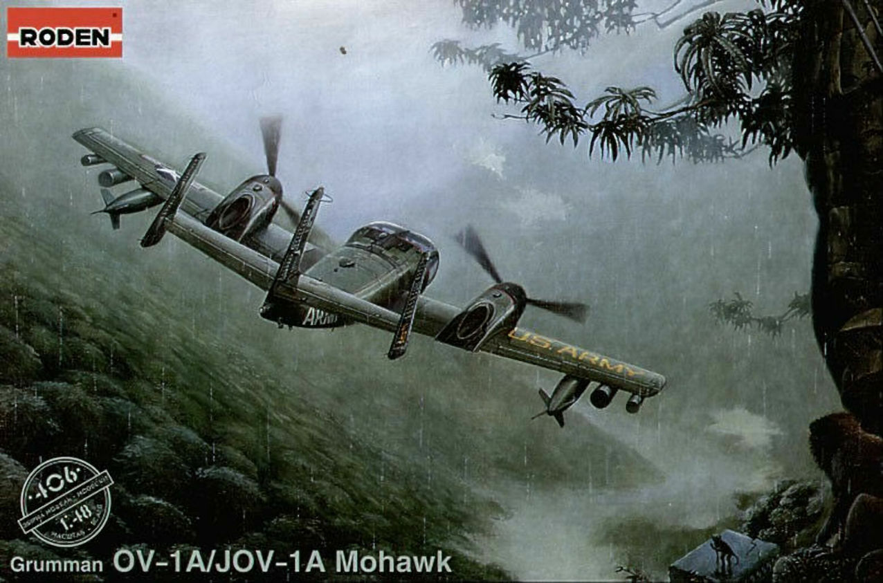
This kit contains six sprues with 156 parts including 18 clear parts. The decal sheet has markings for four aircraft with extensive stencilling in both black and white. White is used for two versions and black for the other two. Optional disposable stores consisting of two drop tanks, two 7 rocket launcher (skinny cylinder), two multiple rocket launcher (fat cylinder) and two 50 cal machine gun pods. There is a 12 page instruction sheet with aircraft history and separate diagrams for aircraft stencils ans a poster of the box artwork featuring the aircraft flying low in a jungle scene and two monkeys.
Construction. (We all know how to stick a to b so main points only)
Dashboard
The first piece built is the aircraft dashboard. The instrument panel consists of a clear part with raised details. A decal is provided for the instruments that is applied to the back of the part. The adhesive is on the front of the decal. The instrument bezels can then be painted. There are two instrument panels supplied in the kit, one is for the SLAR version aircraft and has a different layout of instruments, be sure to use the correct panel or the decal won’t line up. The top of the dash also has a slot for mounting of things for the other version aircraft and it should be filled.
Cockpit floor and bulkhead.
The cockpit rear bulkhead attaches to the floor by a butt joint and should be angled rearwards. The bulkhead bottom edge is chaffered to allow this and I placed these parts into a fuselage half to get the angle right. This also revealed that an amount of filler would be required at the edges where the bulkhead meets the fuselage. At this point I decided not to install all the cockpit guts until the floor was installed and this gap fixed.
Ejector seats.
These build up from nine parts each and are very nice. The side ejection handle is very fragile and care must be taken when removing from the sprue. Seat belts need to be added if you’re that way inclined.
Overhead console.
This part attaches to the rear bulkhead. A flat switch panel is bent along a line and attached to the bottom of the console. This part required putty along the edges and to fill some sink marks.
Throttles, & rear panel.
At the rear of the cockpit is a panel that sits between the seats. In front of that goes another box with the throttle levers. This becomes very important later. When mounting the rear box, ensure that it is mounted dead centre or one of the seats won’t fit in.
Nose wheel.
That’s not in the cockpit, but it does attach to the bottom of the cockpit floor. The wheel itself is in two halves which when assembled are pushed between the forks of the undercarriage leg to allow pins to mate with the centre hole. These pins are a bit on the short side, the wheel is easy to get in but doesn’t mount solidly. The undercarriage leg then mounts into the bottom of the floor with two tiny pins mounting slots at the sides. I considered this arrangement to be too weak to support the nose, so I placed some sprue, cut to fit, between the centre of the leg and the floor.
The Dilemma.
A cursory glance at this aircraft will reveal the main features, a long rear fuselage with a triple rudder and a stubby nose and forward set wing. Couple that with a tricycle undercarriage and you have a model that will need a bucket load of weight to keep the nose on the deck. The instructions do not state how much is required or even say to put any in. If you follow the instructions, the cockpit is sandwiched between the fuselage halves, this will severely limit the amount of weight that can be inserted. As the tub could be dropped in from above, I decided to leave the cockpit out until later. This however has it’s own challenges.
Fuselage, Wings, & Tail
All straight forward, wings required a small amount of putty along the root, and again some putty along all seams. There is a slight amount of overlap between the edges of some of the control surfaces on the wing. The exhaust halves should be joined, trimmed and mounted prior to putting the wing halves together as it is difficult to mount properly afterwards. The exhausts are a slightly different length and need re-profiling of the ends. There is also a visible seam in the pipe that needs to be filled and sanded. The pipe has a cap for the inside end that has the engine detail.
The dreaded weight.
With the fuselage, wings and tail together, I started to calculate the weight required. The fuselage nose is separate and has room for a small weight, I left this off until later so that it could be used for fudge factor later. Balancing the body on a pencil at approx the point of the main gear, I started adding weight to the cockpit cavity, and adding and adding…. Three half inch round sinkers later, the thing was close to balanced. Bearing in mind the weight of the cockpit tub, canopy, engine nacelles and nose, yet to be added, I felt two sinkers behind the cockpit bulkhead and a further one in the nose would suffice. I pounded two of the sinkers into cubes with a hammer and glued them to the rear of the cockpit bulkhead. I then made up a small frame out of aluminium flashing to support them should the super glue fail. The whole lot was araldited and put aside to dry.
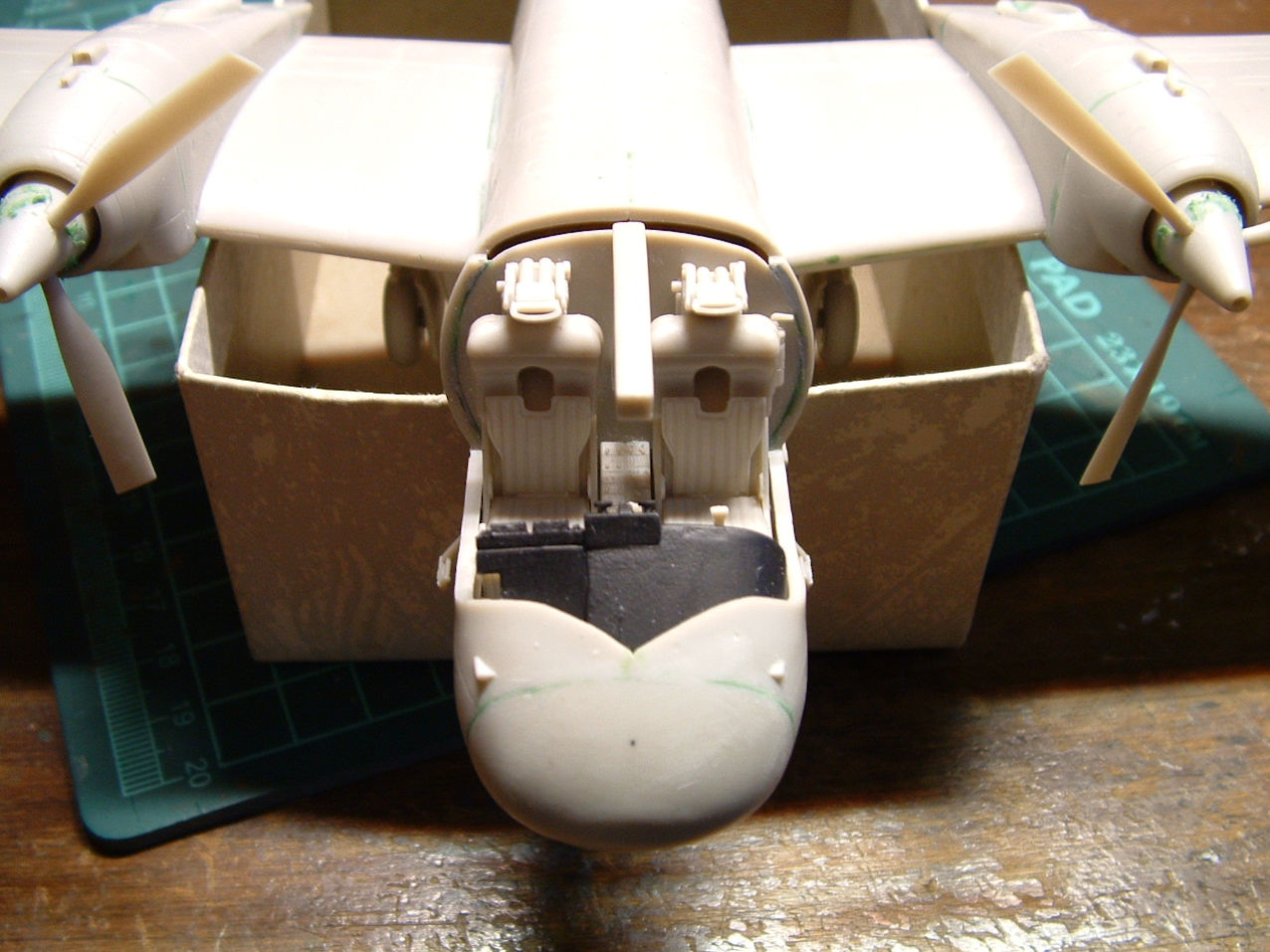
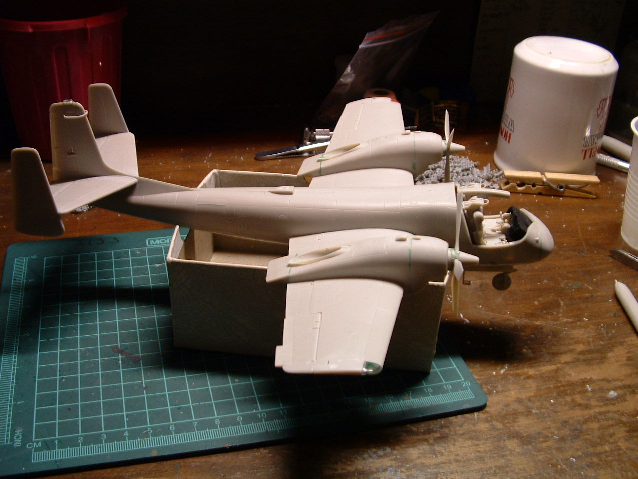
Dropping in the cockpit.
The floor, nose wheel and weight attached was dropped in and the gap at rear of the cockpit fixed. At this point, with the nose wheel protruding the model becomes hard to handle as it won’t sit flat. I made a simple jig by cutting some slots in a small cardboard box for it to sit in.
The challenges mentioned earlier.
Now the fun really starts, shoehorning all the crap into the cockpit. Start first with the rudder peddles as these are under the dash. This stuff should be painted first as access is limited afterwards. Next slide the dash into the slot provided, it will sag a bit but don’t worry about that yet. Next comes the box between the seats if its not already installed and then the panel with the throttle levers. This part forms the support for the dash, is wedged between the box at the back and the panel and is a tight fit. There is a little hand wheel on one side of this panel that needs to be trimmed flatter for the seats to fit later. The bottom of the seats is not a flat surface. The rails at the rear of the seat protrude at an odd angle. These are supposed to mate with a raised square on the floor but are too close together. I trimmed these down as that part could not be seen and installed the seats with the rails running parallel to the rear bulkhead. The fit is tight but if everything else is centred they will fit okay. Finally, the overhead console is attached to the rear bulkhead and the fire extinguisher and control stick added.
Engines, twirly bits, main undercarriage legs.
The nacelles are a touch oversize and need filling/sanding as do the end caps for the engines. Some weight can be added into the nacelles. The prop blades are separate and are captured between halves of the spinner and so can be rotated to any position. The spinner needs careful trimming of the recesses to prevent cracking. The main undercarriage legs are sturdier that the front one, so I used them “as is”. There are struts for the undercarriage covers that are moulded off register but the rest of the kit has no evidence of this.
The dreaded weight revisited
With the undercarriage dry, the aircraft could now stand on its own feet. (main feet and tail at any rate) The nose, left off earlier, was balanced in the cockpit and the remaining sinker dropped on, sure enough the model righted itself. I had enough weight, it was now a matter of fitting a round sinker into a square hole, well vaguely pyramid like. The hammer was utilised to pound the sinker into a shape matching the nose. Several flat fingers later, I had a weight conforming to the inside of the nosecone, but overhanging to the rear, it would not fit in the space. Abandoning that idea, I next tried filling the nose with lead shot. This worked eventually after pounding the shot into less space wasting shapes than spheres. The nose was attached, and even without the canopy glazing, the nose would return to the ground after being lifted a centimetre.
Disposable Ordinance
This is optional, two of the supplied decal versions do not have the weapon stations fitted. The ordinance supplied is not up to the standard of the rest of the kit. The drop tanks suffer from long sinks and the halves do not fit neatly together. Each halve has a separate fin that needs trimming of the base to install in a slot. The actual mounting points to the station are tenuous at best. I chose not to add extra weight into the tanks because of this.
Summary
Good moulding and details. If the aftermarket crowd comes up with a pewter nose wheel and leg, it will be a worthwhile addition. My example had some broken parts, the most serious of which is a crack right through the middle of the right hand windscreen. Other than that, it’s a good value and high quality model.
Steve Pulbrook
February 2005